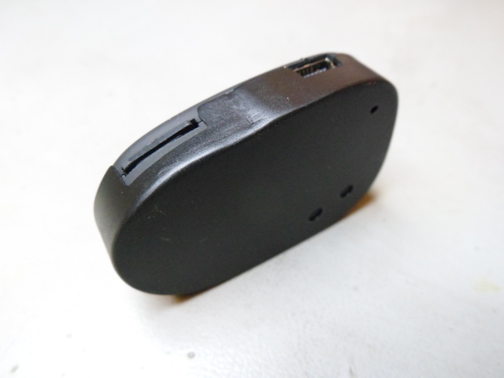
#11 Keychain Protection Casing
How to build an External Protection Casing (half case) for the #11 keychain
This page is linked from the original posting at Tom's RC Groups page found at www.rcgroups.com/forums/showpost.php?p=19181057&postcount=6408.
The buttons on the #11 are extremely sensitive and during use I was always inadvertently pressing them. Since there is no indication if the camera is recording or not, I looked for a way to solve this problem. I also wanted to protect my cameras from self-starting, and thus discharging, when carrying them in my pockets.
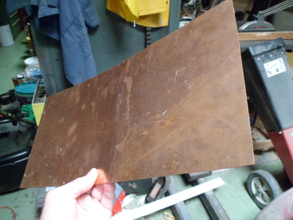
At first I considered using plastic, but decided against this material because of the difficulties I would have in cutting and glueing the parts. If you have the right eqiupment I'm sure this is possible and maybe even a better solution. Anyway, then I considered tin from an old can of whatever. However, tin easily rusts, so I decided against this. Obviously you can't use aluminum (soft drink cans) because it can't be soldered. Looking in my garage, I found a piece of copper "repair" panel that I had bought years ago. Copper is great for soldering, and with soldering there is no waiting for glues to set. Copper doesn't rust, but it does corrode. However, corrosion isn't as bad as rust, and I would paint the final project anyway. Using tin would also be possible though. Unfortunately, copper is fairly heavy, so I don't think this project is suitable for small RC airborne projects. The finished case weighs approx. 8 grams.
I'm sure someone has developed a simpler case, but I haven't found it, so I hope this idea is useful to somebody. Maybe it can be adapted. I need a tight fit, so using a tic-tac casing, or similar, is not a solution for me.
Now I'll show you how I built my casings in a couple of hours. Luckily I had all the tools required, mainly a piece of 0.3 mm thick copper "repair panel", small metal cutting shears, a good wide soldering iron (mine is almost 40 years old) capable of going very hot, thin (0.5mm) leaded solder, flux (not really needed), 1 mm copper wire (can be substituted with strips cut from the copper board), a can of matt black spray-paint, and acetone or thinners for cleaning up. I find Acetone better than thinners because there is no residue.
Copper with a thickness of 0.3 mm is ideal. If it is thicker it will be difficult to bend, so I would say the motto here is "the thinner the better".
The copper must be bright and clean before soldering. You can use wire wool or scouring pads or scouring powder under warm water. I used a combination of scouring pads and powder. I rinsed using washing-up liquid and plenty of water. If the copper is not bright and clean it will be all but impossible to get clean solder joints because the solder won't "flow".
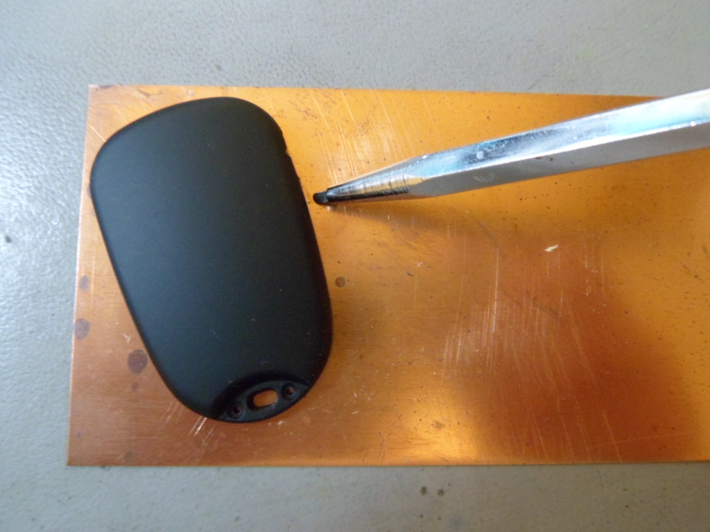
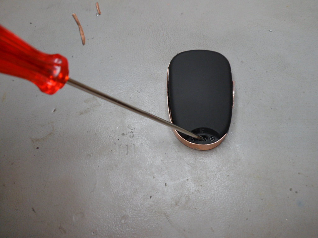
First of all, I opened up the camera and put the 4 screws and circuit board and plastic buttons in a safe place. The two halves, well, actually only one of them, is used for drawing the outline shape and marking the position of the buttons and LED.
Here's the piece of copper I used to start with.
Using a pointed object, draw around 1 half of the camera shell to scour the outline. This should be done as accurate as possible.
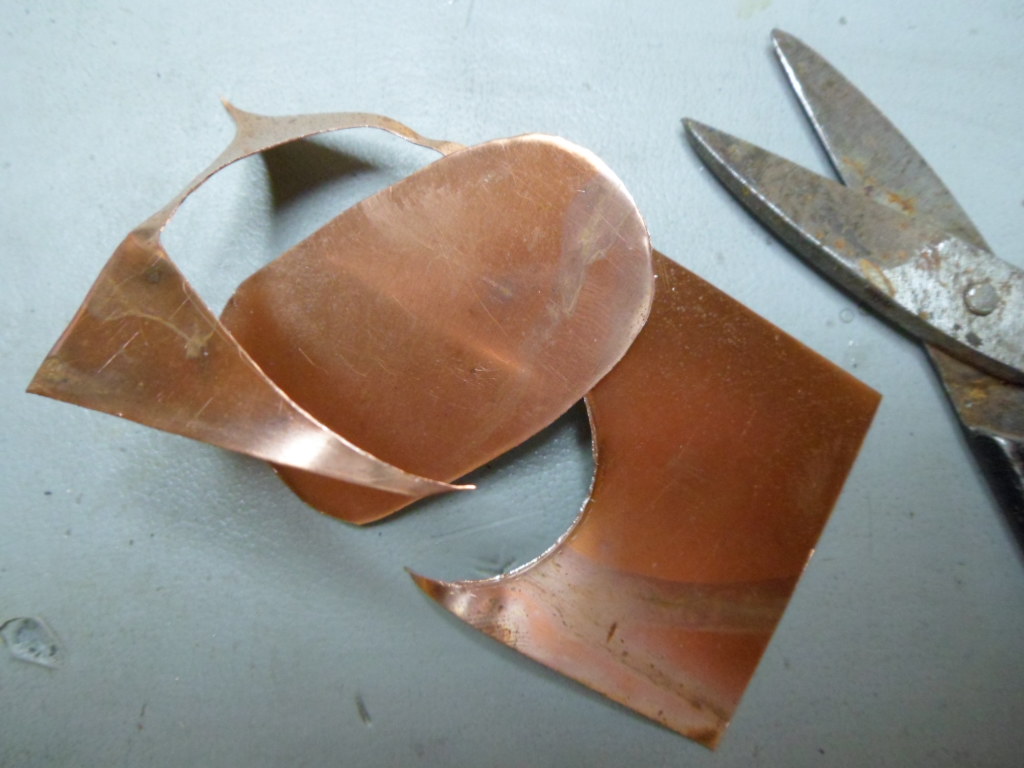
Now, use a small pair of tin-snips to cut out the shape. It's important that the cut out is always straight and there are no bends or creases.
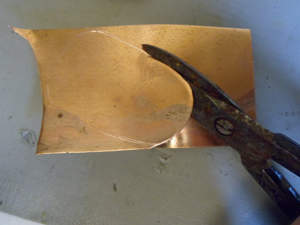
This is how my cut-out looked.
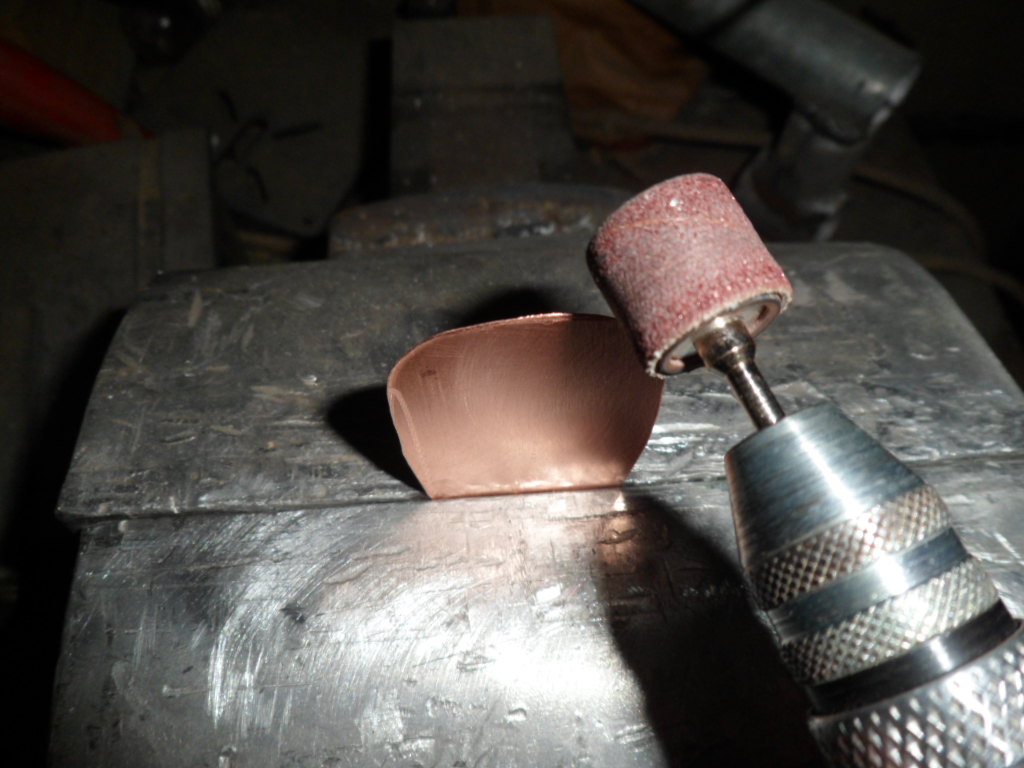
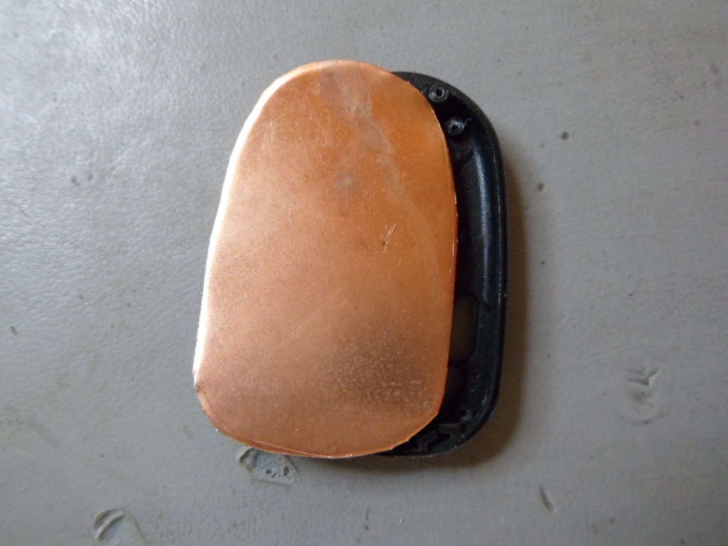
Use a file, sandpaper or a mini sanding disk for removing any jagged edges. The cut-out should match the casing fairly well, but it doesn't have to be perfect. It must not, however, be undersized!
Here's a picture of the cut-out together with half the casing.
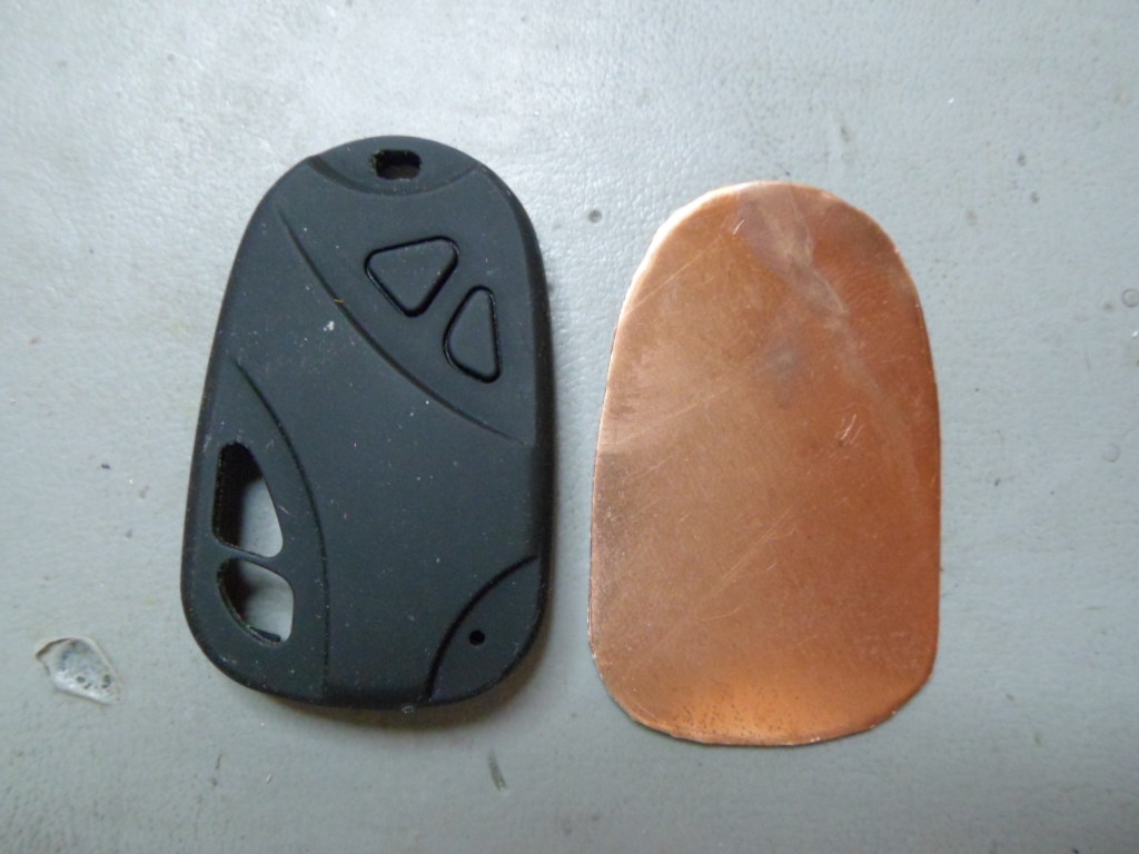
The match is pretty good.
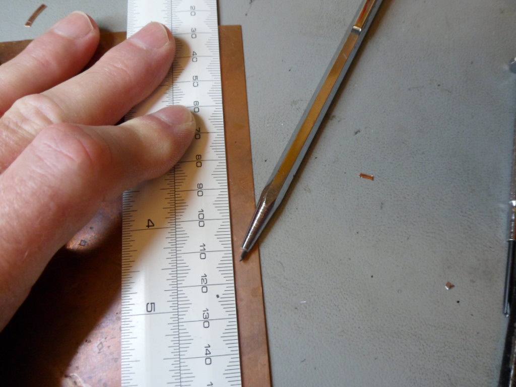
Now I scoured the markings for the side strip. This should be between 7 and 8mm wide.
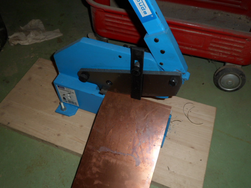
I'm lucky to have a table shear to cut straight strips of metal, but hand-held metal cutting shears or tin-snips will also do the job.
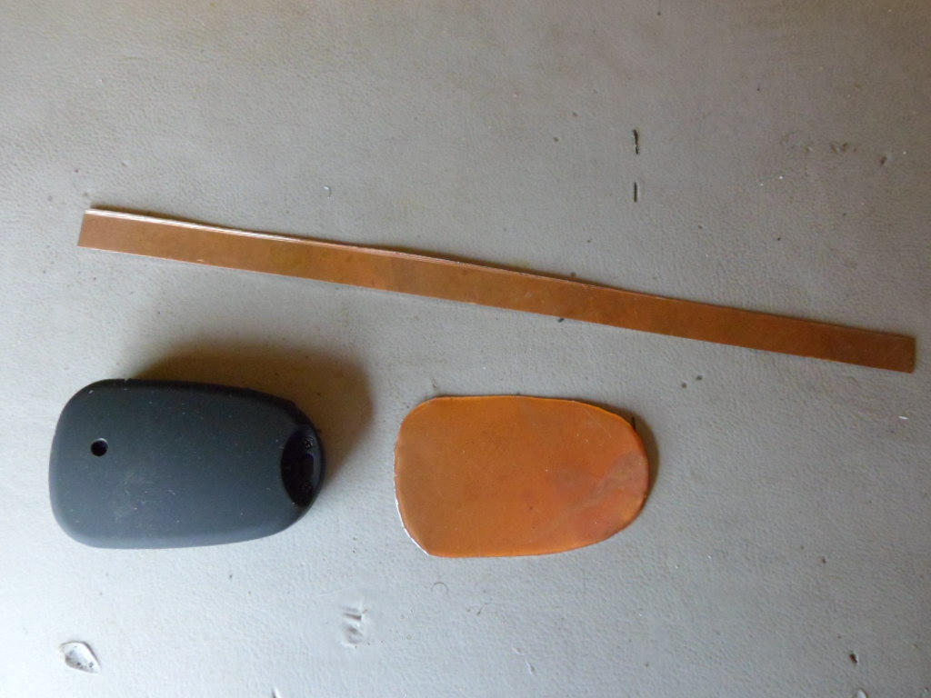
Here's a picture of the main parts. I adapt my cameras for the lens on the side, that's what the hole is for. Obviously, the original camera does not have this hole.
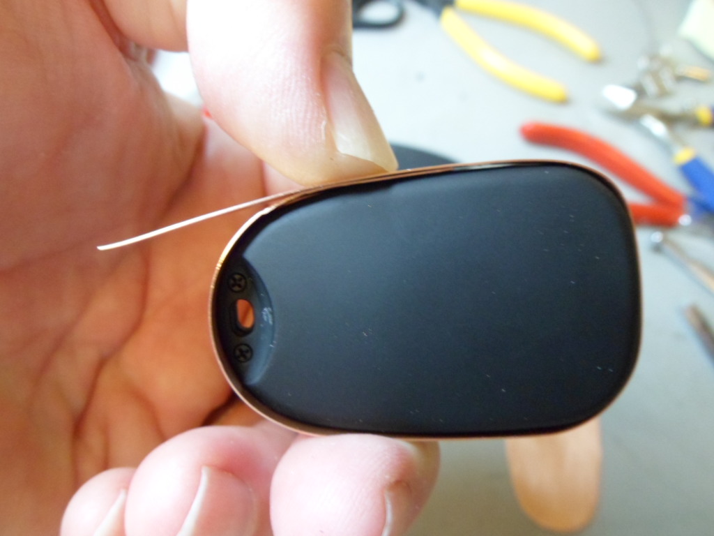
I now cleaned both copper parts with scouring pads and powder until the copper was nice and shiny. I rinsed the parts in washing-up liquid and lots of water. The next few steps are quite tricky. First, I "wrapped" the side strip around the camera to get a tight fit. - picture taken with a new camera body, no hole yet!
After cutting off the excess copper to allow a 5 mm overlap, I marked the copper where the join would be. This is quite critical.
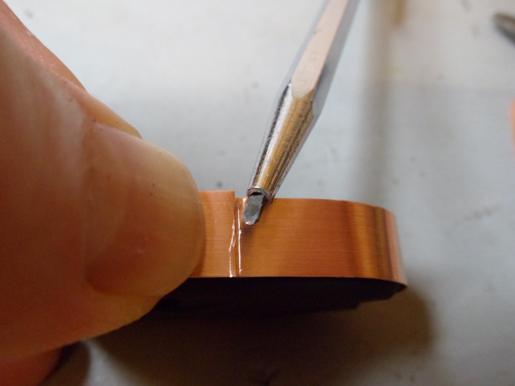
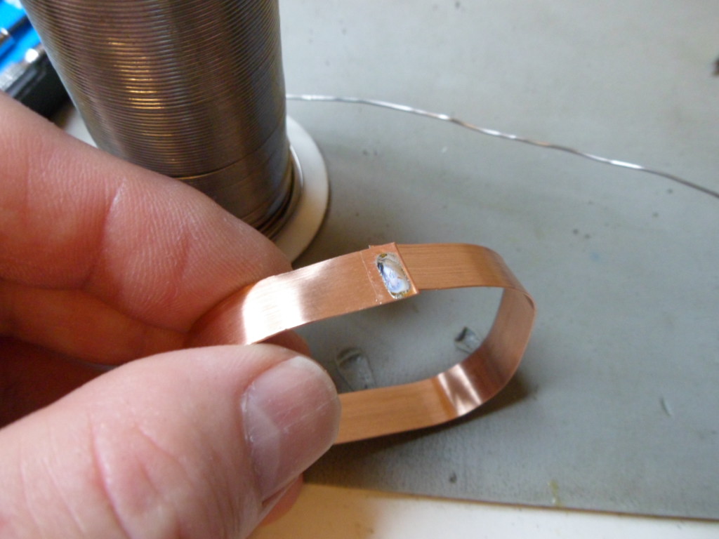
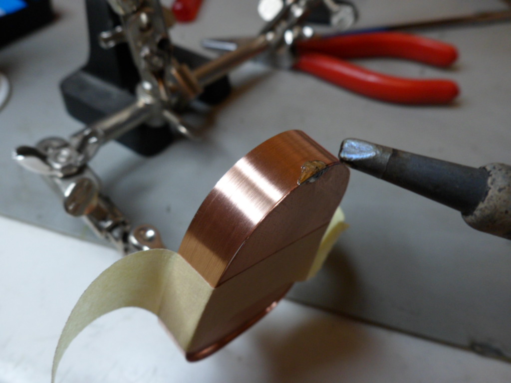
This picture shows the side ready to be soldered. I applied flux to the two inner ends that would be joined.
I put on a small bead of solder to both inner parts. The soldered part in the picture will be soldered below the end on the right. If you have a very hot soldering iron this isn't necessary.
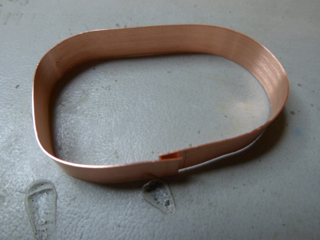
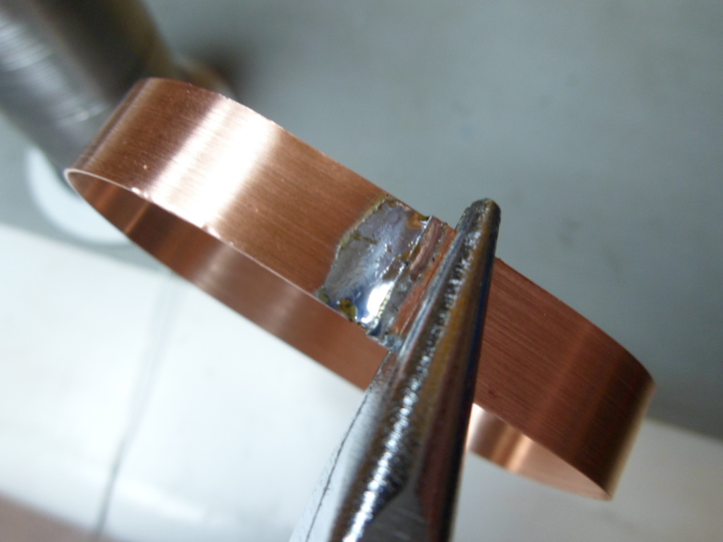
And joined them together. This is tricky because the joint should be as flush as possible. Pliers act as a heatsink, making it difficult for the solder to melt. Avoid too much solder on the inner side. Excess solder must be removed by filing/sanding.
Now I double-checked that the camera fitted snuggly into the copper side.
I aligned the bottom with the side and held both pieces into position using masking tape. Then I made the first solder tack to hold the two pieces together. Applying plenty of flux to the edges helps the solder to adhere and run smoothly.
The side is now solder-tacked in place. Don't solder near the overlapping side joint or the heat will unsolder the joint and it will be difficult to get a clean join again.
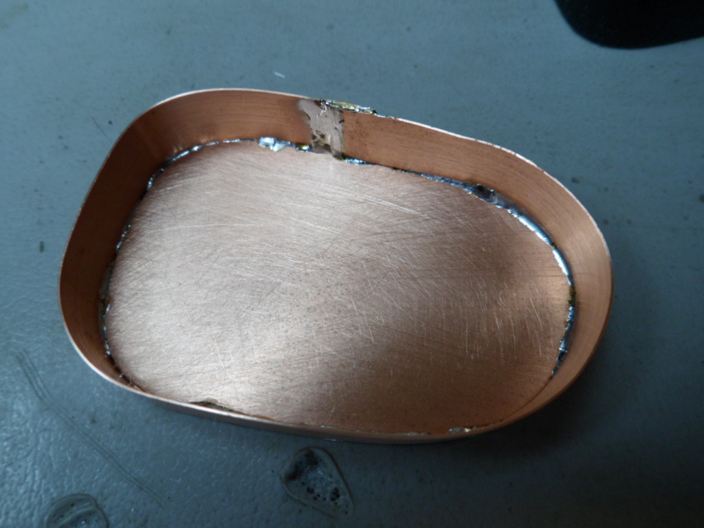
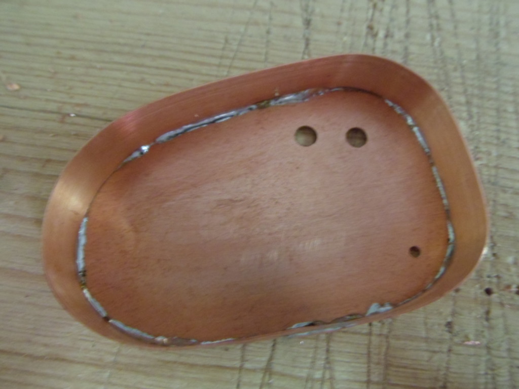
Now I put a thin solder bead along the complete join. Again, pay special attention when you solder near the overlapping side joint. Although the bead looks a bit messy in the picture, it was, in effect perfectly OK.
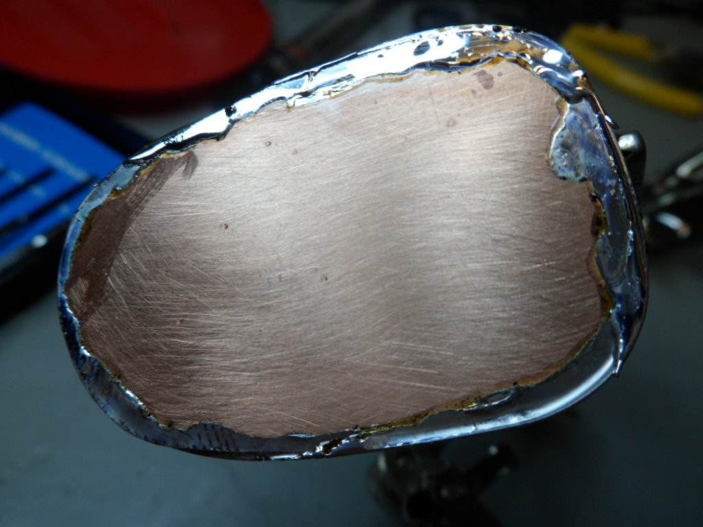
Here's a view of the inside. Not a perfect bead, but very acceptable and most probably also waterproof! For best results, the join should be on the opposite side as shown in the picture. On all my prototypes so far I've got this wrong!
Now I marked the center of both buttons.
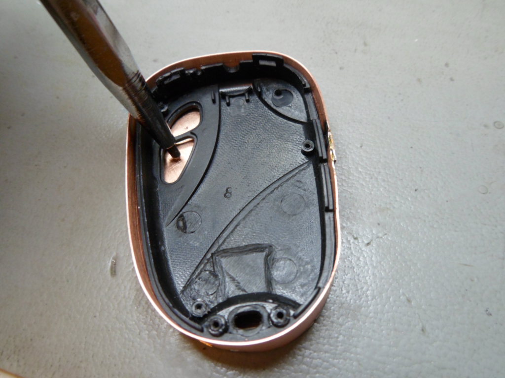
For the LED hole you'll need a very thin pointed instrument. I used a mini screwdriver, but you could use a small drill bit or some other thin-pointed instrument.
Using a 1 mm drill bit, I drilled the three pilot holes. Make sure the drill is sharp (new).
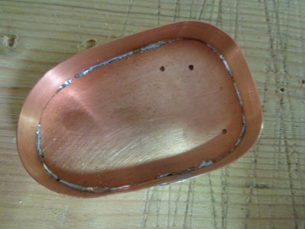
I enlarged the two "button" holes to 3.5 mm and the LED hole to 1.5 mm
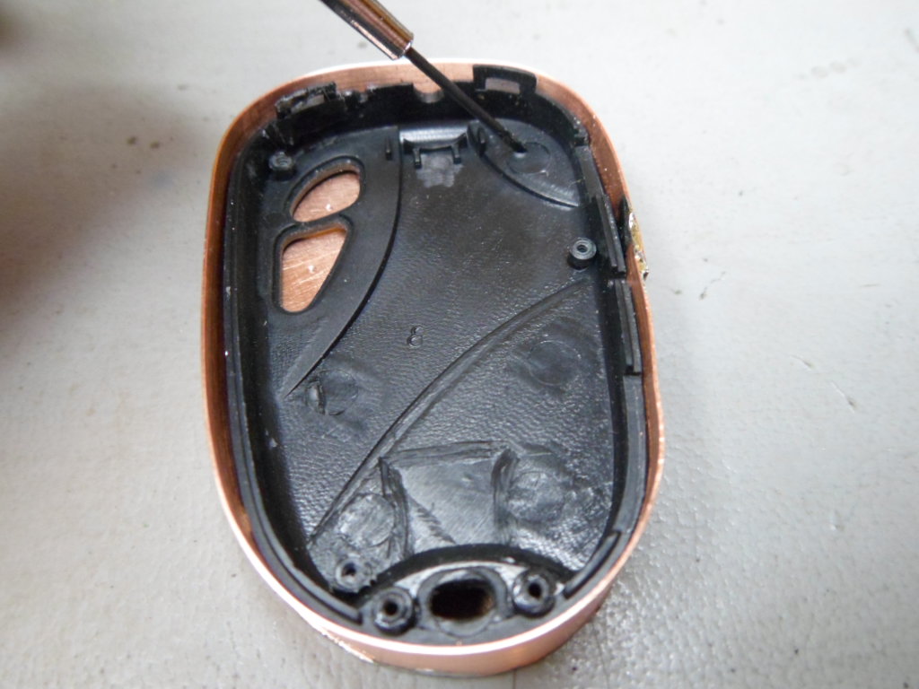
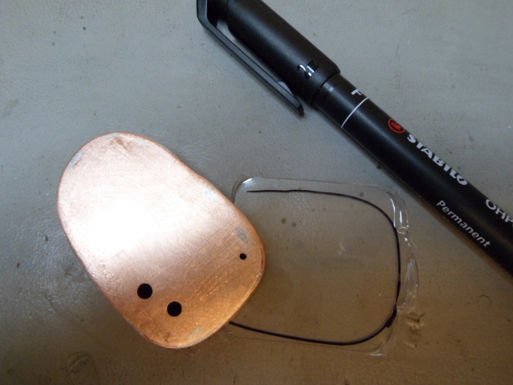
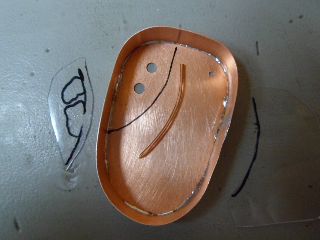
Since the camera case is rounded, the buttons can still be activated by pressing on the copper casing if the camera is moved inside the casing. To eliminate this problem the camera needs extra support so that it can't "wobble" in the metal casing. To determine the correct position for this extra support - a piece of wire - some form of template is needed. I used a piece of trash plastic for my template. Tracing paper would also be fine. I traced the outline of the case.
Now I cut out the template, a bit undersized, and traced the positions of the buttons, but more importantly the recessed line between the buttons and the casing.
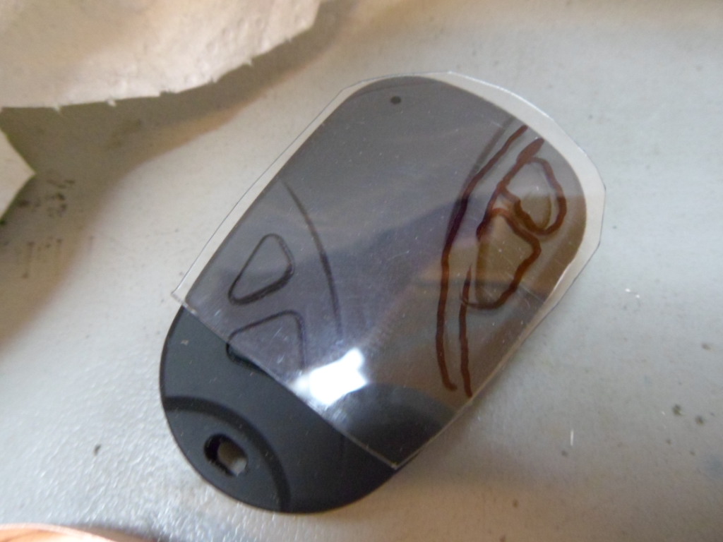
I transferred the outer edge of the line onto the copper by first cutting along the line on the plastic. The plastic template must be followed upside-down!
Now I cut a piece of wire to follow the shape. The wire should be 1 mm in diameter. I didn't have this wire at hand, so I used a piece of 1.5 mm wire and compressed it into 1 mm using a vice. It is also possible to cut out a few "wires" from the copper board and solder them in layers. 3 layers is perfect - 3 x 0.3 mm = 0.9 mm plus solder equals approx. 1 mm.
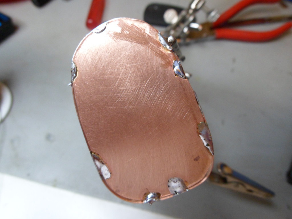
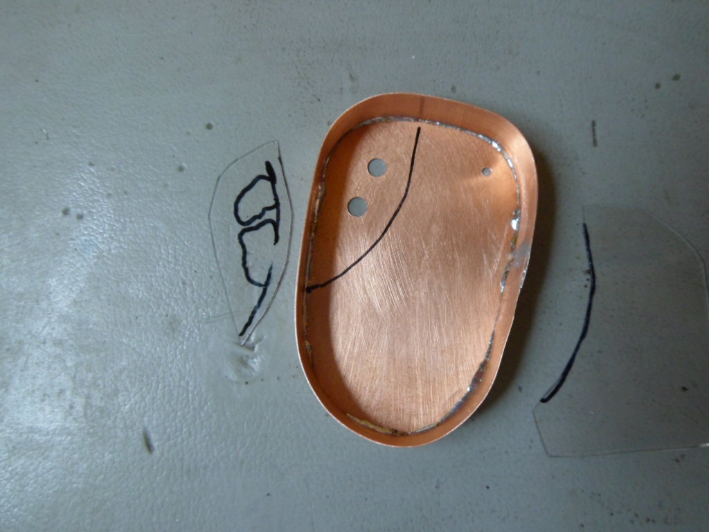
Here you can see the wire soldered into place.
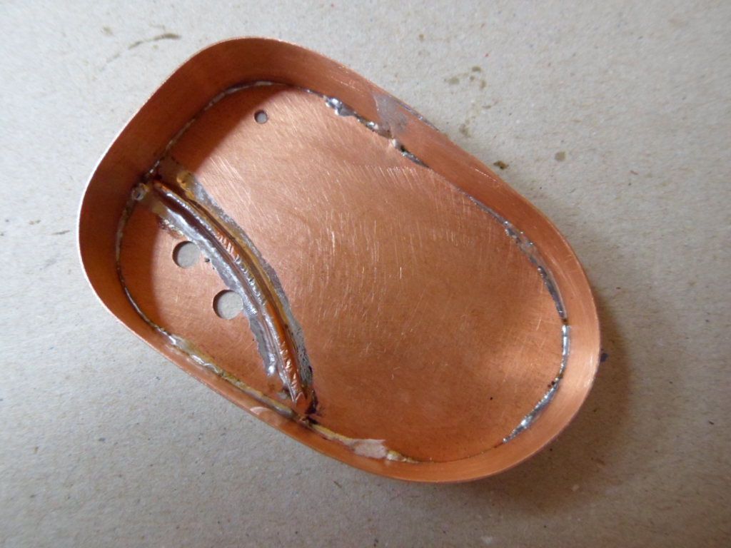
Unfortunately, a bit more protection is still required. I added these to both front corners. Since the positions are not critical, I judged where the wires should be soldered. I didn't do a very good job on the right side!
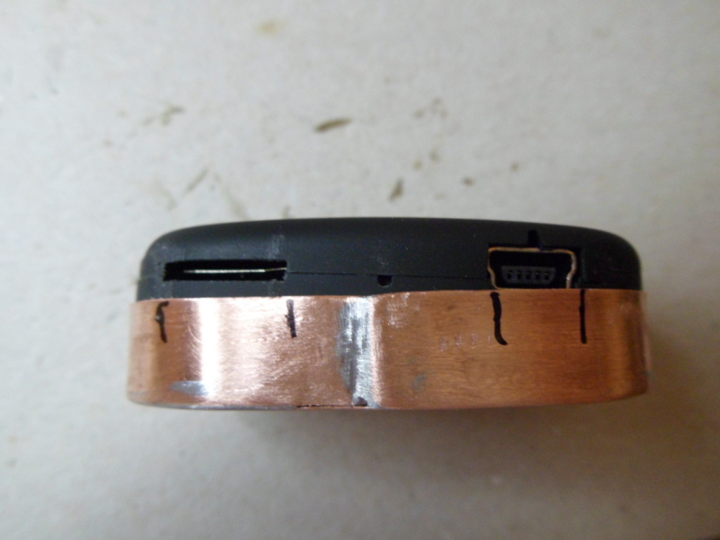
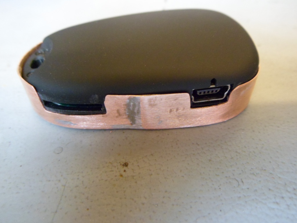
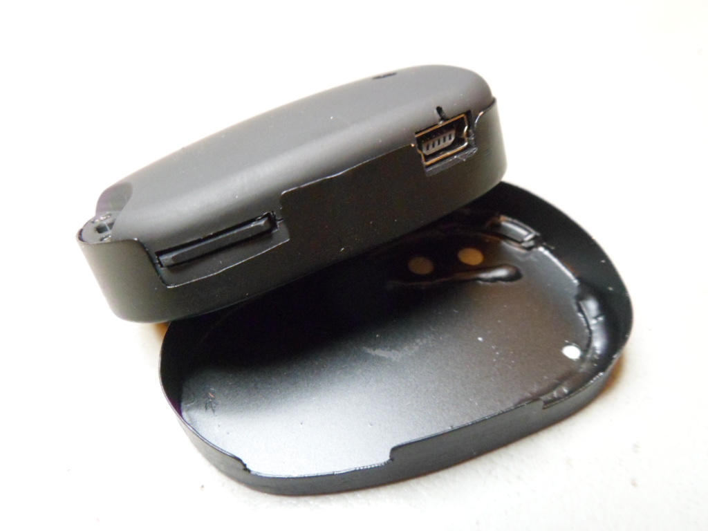
Since I use the case protection while recording, I needed to cut out holes for the card slot and the Mini-USB socket. Normally, you will also need a cut out for the lens. However, since I have converted my cameras to record from the back (the side opposite the switches), I don't need this hole.
Once inserted, it's difficult to remove the camera from the casing. Use a small screwdriver or attach a piece of string to the hole designed for this purpose.
I used a mini grinding disk and a flat file. It's possible to do this with the file alone, but it would take longer. Be careful not to inadvertently bend the corners
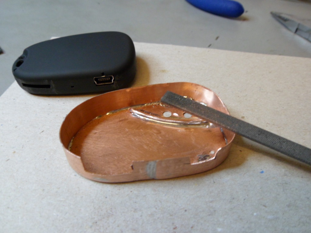
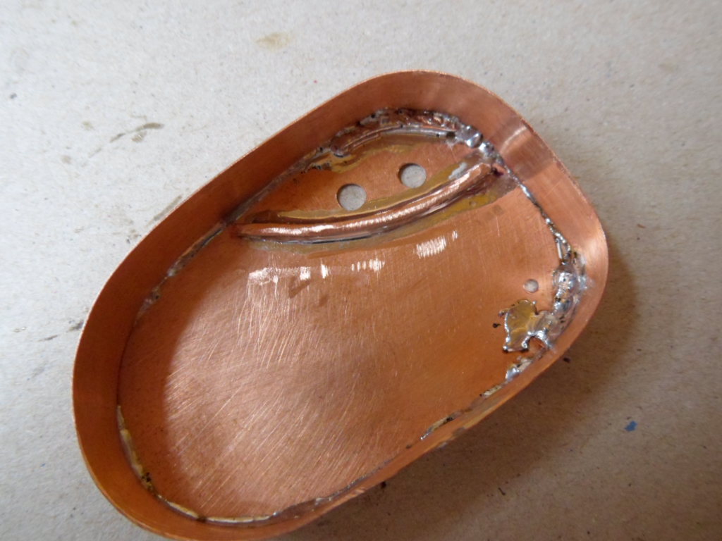
I was satisfied with the results below. Now all that is needed is to clean up all the edges using wet-or-dry 300 grit sanding paper.
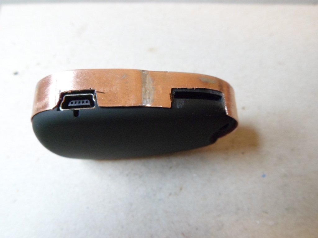
These are the results you can expect after a light rubdown using wet-or-dry 300 grit sanding paper.
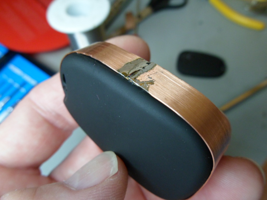
And painted, it looks much better. Here are two cases, one with the camera inside the case
Summary
For perfect results you should make the side-join on the side opposite the USB socket / card slot. On all my prototypes so far I got this wrong!
If you need to be certain that the copper casing doesn't inadvertently fall off, you can use a piece of tape wrapped around the camera/casing. However, if you have followed my instructions correctly, and used copper no thicker than 0.3mm, the casing should be a very good fit.
If you have converted you camera to have the lens rotated by 90° like in the 10th picture, the copper case provides an excellent support for attaching to flat surfaces.
It may be possible to use glue instead of solder. I haven't tried this. It may also be possible to use a hot-air gun with a small pointed "blower" instead of a soldering iron but I also haven't tried this. A hot air soldering iron would certainly work, but I doubt that most people would have one of these.
I hope these instructions are useful for somebody. Also, I would like to hear if someone has attempted this project with tin from a tin-can. It would also be good to see other modifications / ideas posted on Tom's original thread at: http://www.rcgroups.com/forums/showthread.php?t=1362692.
Thank you for reading.
Isoprop
Last updated: 29th August 2011